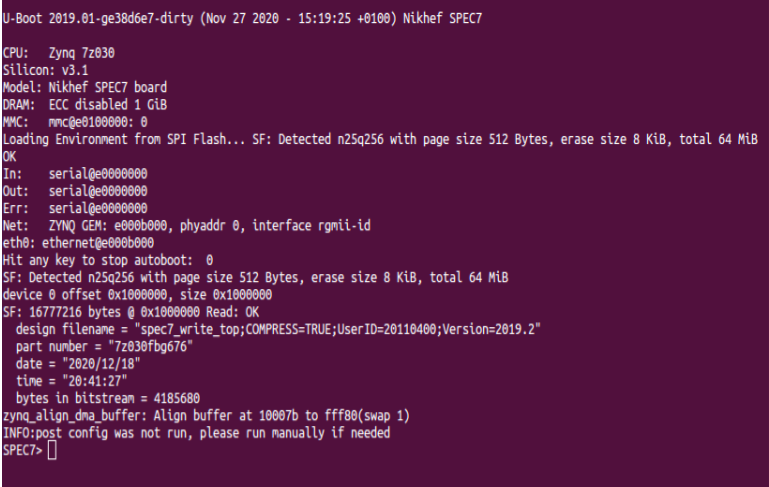
U-boot
U-Boot is a universal bootloader and is responsible for booting the Linux OS on the Zynq based SoC. It i sa powerful second-stage bootloader with many capabilities. U-Boot provides a command-line interface (CLI) on the serial port of the Zynq MPSoC. The CLI offers commands for reading and writing flash memory, device-tree manipulation,downloading files through the network, communicating with hardware, etc. It even offers the use ofenvironment variables, which can store sequences of commandsOn top of that, it can also run Hush shell scripts.
Build
Require:U-boot-Xilinx clone for SPEC7
Setup the environment for cross-compilation:
$ export CROSS_COMPILE=arm-linux-gnueabihf-
$ export ARCH=arm
Get the sources
$ git clone https://ohwr.org/project/spec7-firmware.git
$ git checkout spec7_custom
3. SPEC7 Config
All config files are located at configs/
$ make zynq_spec7_defconfig
check config also using menuconfig
$ make
This will generate
u-boot.elffile in the same repository
U-boot can directly be built using Makefile and sources in spec7 ohwr repo ,run:
$make
This will generate u-boot.elf in ../output directory
To clean up:
General U-boot shell commands
printenv - Print the U-boot environment variables
ipaddr- Check IP Address of board
ethaddr-MAC Address
re- reload bootloader
tftpboot- Load file from tftp server
fatls - list files present in mmc
mmc - to query and check sd card
setenv - define and redefine a new environment variable
dhcp - run dhcp client and fetch IP for board if defined in network
Reconfigure FPGA using U-boot shell
Introduction
In order to load a secondary gateware from QSPI, we first need to write our gateware in some known offset of the QSPI. Once the secondary gateware is written to the QSPI, U-Boot must be able of loading it on the Programmable Logic at booting time as fast as possible.
In the SPEC7, we have a 64 MiB QSPI and we initially had three different supported Zynq-7000 devices, with the following bitstream sizes:
Device |
Bits |
Bytes |
MiB |
|---|---|---|---|
7Z030 |
47839328 |
5979916 |
5,66 |
7Z035 |
106571232 |
13321404 |
12,61 |
7Z045 |
106571232 |
13321404 |
12,61 |
Despite the fact that some of the first prototypes were mounting the 7Z030 device, this device have been discarded for production due to technical issues. In this way, we can consider a gateware size of roughly 12,61 MiB for all of the production SPEC7.
In this way, we propose to divide the QSPI in the following layout:
Slot |
Offset (Bytes) |
Size (Bytes) |
Size (MiB) |
0 |
0x0000_0000 |
0x0100_0000 |
16 |
1 |
0x0100_0000 |
0x0100_0000 |
16 |
2 |
0x0200_0000 |
0x0100_0000 |
16 |
3 |
0x0300_0000 |
0x0100_0000 |
16 |
Each of the offset are dedicated to:
- Slot 0: contains the FSBL, the golden gateware and the U-Boot binary.
- Slot 1: contains the first secondary gateware
- Slot 2: contains the second secondary gateware
- Slot 3: contains the third secondary gateware
Overriding the default boot process
By default, u-boot includes a pretty complex boot sequence that scan for multiple local and remote boot targets and that is designed to boot a whole Linux runtime in the Processing System.
The command that starts the execution is contained in the bootcmd variable of the u-boot environment.
As an example, by overriding the bootcmd with a simple message and saving the environment, we will directly break into u-boot prompt:
SPEC7> setenv bootcmd "echo Break for testing"
SPEC7> saveenv
Once done, we can check this by resetting the SPEC7 platform from U-Boot:
SPEC7> reset
Updating the gateware in QSPI
In order to demonstrate how to program the gateware in the bitstream, we will consider that we want to copy a bitstream to the Slot 2, i.e. offset 0x0200_0000.
Using JTAG:
We have two different approaches to load the gateware to the QSPI via the JTAG: - Include the gateware in the complete boot image to be writen in QSPI - Program the gateware as an independent binary blob in an already programmed SPEC7.
Include the gateware in the boot image
We create a boot image with an additional data partition containing the gateware in which we specify the offset, e.g. 0x0200_0000.
Note that we could use any of the available offset or, if required, add as many data partitions and respective offsets as different secondary gatewares we want to program in the QSPI.
Is important to note that the Vitis Boot Image generator and the FLASH programming tools only accept .bin and .mcs files.
The MCS file is a HEX file where two ASCII chars are used to represent each byte of data, while the binary file just contains the raw byte stream in sequence.
So the MCS file seems less efficient, because it takes 2 bytes to represent 1 byte, but it has a couple of advantages: - (1) It has a checksum at the end of each line for integrity. - (2) Each line includes the address where the line should be located in memory.
So for example, if a MCS file contains a few segments located far apart in address space (e.g. a gateware in the second or third QSPI slot), it can be small while the equivalent binary file might be huge, because it would have a lot of 0x00 or 0xFFs to fill the space between segments.
Program the gateware as an independent binary blob
If we want to program the gateware as an independent binary blob, we just need to use the Vitis FLASH programming tool and: - select the gateware a data image to be writen. - select the desired offset for the data to be writen, e.g. 0x0200_0000.
Note that the gateware can be generated in standard bitstream (.bit) or binary (.bin) format. Because the Vitis FLASH programming tool only accepts files in bin and mcs formats, if we are going to write a bitstream gateware, we will need to modify the file extension from .bit to .bit.bin so that the tool is able to load it to QSPI.
Using U-boot
We can use U-Boot drivers to access the supported peripherals in SPEC7 to: - load the gateware in a known location at the Processing System DDR. - copy the gateware in the DDR to the intended slot at the QSPI.
Note: the DDR offset in which we will load the gateware is defined in the pre-defined ${loadbit_addr} variable at u-Boot environment, but you can customize to any addressable value. By default, this is the value: .. code-block:
loadbit_addr=0x100000
Copy the gateware to DDR from a microSD card
Copy all of the bitstreams you want to test into a FAT32 formatted partition in the microSD, then insert the card in the SPEC7 and boot.
If you hot-plug the microSD card when u-boot is running, you will need to re-scan the MMC devices:
SPEC7> mmc rescan
SPEC7> mmc info
List the contents of the first partition to check that your bitstreams are there:
SPEC7> fatls mmc 0:1
4045672   new_gateware.bit
4045564   new_gateware.bin
2 file(s), 1 dir(s)
Now, we can copy to DDR the desired bitstream by:
SPEC7> fatload mmc 0:1 ${loadbit_addr} new_gateware.bit
or, alternatively:
SPEC7> fatload mmc 0:1 0x100000 new_gateware.bit
Copy the gateware to DDR from a USB drive
Copy all of the bitstreams you want to test into a FAT32 formatted partition in the USB, then insert the drive in the SPEC7 and boot.
The following command to start the USB driver:
SPEC7> usb start
And this one to stop it when you are done:
SPEC7> usb stop
This command perform a complete re-scan of USB devices when you hot-plug the key:
SPEC7> usb reset
In order to list the content of a FAT formatted partition, you use this command:
SPEC7> fatls usb 0:1
Then, as an example, if you have a gateware in your USB FAT partition, you load it to memory by:
SPEC7> fatload usb 0:1 ${loadbit_addr} gateware.bit
or, alternatively:
SPEC7> fatload usb 0:1 0x100000 gateware.bit
Copy the gateware to DDR from a TFTP Server
If we have a TFTP server in a host computer connected to a Ethernet network in which the SPEC7 is residing, we can deploy the desired gateware file in the TFTP shared folder so that the SPEC7 can retrieve it.
Once the TFTP server is properly configured, we need to configure the server ip in the SPEC7 via the U-Boot serverip environment variable:
SPEC7> set serverip <host_pc_ip_address>
SPEC7> saveenv
Now, we can load the gateware bitstream to the DDR memory by just:
SPEC7> tftpboot ${loadbit_addr} gateware.bit
or, alternatively:
SPEC7> tftpboot 0x100000 gateware.bit
Copy the gateware to DDR from a serial port
In some development setups, it might be useful to load a gateware to DDR by using the same serial connection we are using for the U-Boot prompt.
This is a complex task that can be accomplished with different serial file transfer protocols. As an example, we have included an additional wiki page with detailed instructions on how to perform a [serial file transfer with Kermit](serial-file-transfer-with-kermit).
Copy the gateware to QSPI from the DDR
Once the desired gateware have been copied to the DDR, we can move the file contents to the destination QSPI slot.
As an example, we will focus in using Slot 2, i.e. offset 0x0200_0000.
In order to do this, we activate the QSPI flash and erase the associated 16MiB slot:
SPEC7> sf probe 0 0 0
SPEC7> sf erase 0x2000000 0x1000000
Finally, we can move the gateware from DDR to QSPI: .. code-block:
SPEC7> sf write ${loadbit_addr} 0x2000000 ${filesize}
Note: the ${filesize} value gets automatically updated with the size of the last file that has been loaded to DDR.
Programming the FPGA by using U-Boot
Load the gateware from DDR to FPGA
Once we have a gateware in the DDR memory, we can use the appropriated command to load it into the FPGA depending on the its format.
If the gateware is in .bin format, we use this command:
SPEC7> fpga load 0 ${loadbit_addr} ${filesize}
If the gateware is in .bit format, we use this command:
SPEC7> fpga loadb 0 ${loadbit_addr} ${filesize}
Automatic gateware update from QSPI
In order to allow for automatic loading of the gateware from QSPI using the UBoot, first we define the following environment variables:
SPEC7> setenv bootdelay "0"
SPEC7> setenv gateware_size 0x1000000
SPEC7> setenv qspi_gateware_offset 0x2000000
The meaning for each of these variables are:
- bootdelay: this contains the maximum value of the countdown that UBoot perform before executing the bootcmd. By setting it to zero, we save a precious time at startup.
- gateware_size: we define this auxiliary variable that specify the size of the slot containing the gateware that we want to move from QSPI to DDR. We set the value to 16 MiB, i.e. the full size of the slot.
- qspi_gateware_offset: we define this auxiliary variable containing the QSPI offset of the slot containing the gateware we want to load. In this case, we are pointing to the Slot 2, but we can easily modify the slot to be used by editing this variable.
Now, we create the boot command to read the gateware from the desired QSPI slot to DDR, then from DDR to FPGA, and finally go back to the U-boot prompt:
SPEC7> editenv bootcmd_gateware
edit: sf probe 0 0 0 && sf read ${loadbit_addr} ${qspi_gateware_offset} ${gateware_size} && fpga loadb 0 ${loadbit_addr} 0x1
Note: because we are using bitstream in bit format, the fpga loadb command doesn’t require the exact size of the bitstream, just a non zero value, as the size is already encoded in the bitstream header.
In order to boot execute this command at start-up, we must assign the bootcmd variable and save the environment:
SPEC7> setenv bootcmd "run bootcmd_gateware"
SPEC7> saveenv